Table of Contents >> Show >> Hide
- What Is 3-Way Switch Wiring?
- Key Parts and Cables in a 3-Way Circuit
- Safety First: Before You Touch a Wire
- Tools and Materials You’ll Need
- 3-Way Switch Wiring: The Basic Circuit Layout
- Step-by-Step: How to Replace 3-Way Switches
- Step 1: Shut Off Power and Test
- Step 2: Pull Out the Old Switch
- Step 3: Identify and Label Each Wire
- Step 4: Disconnect the Old Switch
- Step 5: Connect Wires to the New 3-Way Switch
- Step 6: Fold the Wires and Reinstall the Switch
- Step 7: Repeat on the Second Switch
- Step 8: Restore Power and Test the Circuit
- Common Mistakes to Avoid
- When You Should Call an Electrician
- Upgrading 3-Way Switches: Dimmers and Smart Controls
- Real-World 3-Way Switch Wiring Experiences (Extra Tips)
- Conclusion
Being able to flip a light on at the bottom of the stairs and turn it off at the top
is one of those little luxuries of modern life that you don’t appreciate until it stops
working. That simple convenience is thanks to a 3-way light switch circuit. The wiring
looks a bit like colorful spaghetti, but once you understand how it works, replacing or
installing 3-way switches becomes a manageable DIY projectprovided you respect
electricity and work safely.
This guide walks you through how 3-way switch wiring works, the parts involved, and a
practical, step-by-step method to replace existing 3-way switches. We’ll also cover
common mistakes, when to call a pro, and some real-life lessons from the field so you
don’t have to learn them the hard way.
What Is 3-Way Switch Wiring?
A standard single-pole switch controls a light from one location: up is on, down is off.
A 3-way setup uses two special switches to control the same light from two locations,
such as both ends of a hallway or the bottom and top of a staircase. Technically, these
are often called 3-way or 3-pole switches.
Instead of just sending power straight to the light, a 3-way circuit routes power
through two “traveler” paths. Depending on how each switch is flipped, electricity
travels down one traveler wire or the other to complete the circuit and turn the light
on. Change any switch position, and you either complete or break the pathhence the
ability to turn the light on or off from either location.
Key Parts and Cables in a 3-Way Circuit
Common Cable Types: 14/2 and 14/3
In a typical 15-amp lighting circuit, you’ll often see:
-
14/2 cable – one black (hot), one white (neutral), and a bare or
green ground wire. This usually brings power from the breaker to the first switch or
to the light. -
14/3 cable – one black, one red, one white, plus a bare ground. The
extra conductor allows the two 3-way switches to “talk” to each other via the
traveler wires.
Some circuits use 12-gauge (12/2 or 12/3) for 20-amp circuits, but the logic is the
same: the first number is the gauge, the second is the number of insulated conductors.
Wire Color Basics in 3-Way Wiring
-
Black wire – Usually the “hot” wire carrying power from the source
or acting as a traveler between switches. -
Red wire – Frequently the second traveler between switches in a
3-way circuit. -
White wire – Typically the neutral completing the circuit back to
the panel. If it’s used as a hot conductor, it should be marked with black tape to
indicate that it’s not neutral. -
Bare or green wire – Ground, for safety. It doesn’t normally carry
current but gives electricity a safe path if something goes wrong.
Parts of a 3-Way Switch
A true 3-way switch looks similar to a regular light switch but has four terminals:
-
Common terminal (usually black screw) – Connects to the hot feed
(line) or the switched hot going to the light (load), depending on where the switch
is in the circuit. -
Two traveler terminals (usually brass screws) – Connect to the two
traveler wires (often red and black) that run between the pair of switches. -
Ground terminal (green screw) – For the bare or green grounding
conductor.
One important quirk: neutral (white) wires typically do not connect to the
3-way switches themselves. Instead, neutrals are spliced together in the back of the
box or at the light fixture, so the return path stays continuous.
Safety First: Before You Touch a Wire
Electricity is not the place to “wing it.” Before you even loosen a wall plate, take
these safety steps seriously:
-
Turn off power at the breaker. Locate the correct breaker for the
circuit and switch it off. When in doubt, turn off the main and use portable lighting. -
Verify with a voltage tester. Never trust a label alone. Use a
non-contact voltage tester or multimeter to confirm that the wires in the box are
de-energized. -
Follow local codes and permit requirements. Some areas require
permits or inspections even for small electrical projects. When in doubt, check your
local building department or hire a licensed electrician. -
Know your limits. If the wiring looks different from what this guide
describes, or you see aluminum wiring, damaged conductors, or signs of overheating
(melted insulation, scorch marks), call a pro.
General rule of thumb: if you feel nervous, that’s your brain saying, “Let’s get an
electrician,” and that’s perfectly okay.
Tools and Materials You’ll Need
For a typical project where you’re replacing existing 3-way switches
(not running all-new cable), gather:
- Two 3-way switches rated for your circuit (usually 15A or 20A)
- Flathead and Phillips screwdrivers
- Wire stripper/cutter
- Non-contact voltage tester or multimeter
- Electrical tape and labeled stickers or masking tape for marking wires
- Wire connectors (wire nuts or lever-style connectors)
- Replacement wall plates if the old ones are damaged
- Flashlight or work light
If you’re running new wire, you’ll also need the appropriate 14/2 and 14/3 (or 12/2 and
12/3) cables, cable staples, and possibly a drill for routing through studs. New wiring
should only be installed where permitted by code and only if you’re fully comfortable
with basic electrical practices.
3-Way Switch Wiring: The Basic Circuit Layout
There are several ways to wire a 3-way circuit depending on where power enters (at a
switch or at the light) and where the load exits. For most DIYers, the most practical
project is simply replacing two existing 3-way switches using the
existing cables. You’re not redesigning the entire circuityou’re just moving each wire
over to the correct terminal on the new switch.
In a common configuration:
-
Power (line) enters one switch box and connects to the common on the
first 3-way switch. -
Two travelers run between the two switches and connect to the traveler terminals on
both switches. -
The common terminal of the second switch connects to the wire going to the light
fixture (load). - Neutrals stay connected together and bypass the switches entirely.
Even if your circuit is slightly different, the core idea is the same: common is the
“in” or “out,” travelers are the “paths,” and ground is your safety net.
Step-by-Step: How to Replace 3-Way Switches
The easiest, safest DIY approach assumes the 3-way wiring already exists and you’re
just swapping out old switches for new ones.
Step 1: Shut Off Power and Test
- Turn off the breaker that controls the circuit.
-
Try flipping the light switches. The light should stay off regardless of switch
position. -
Remove the switch plate screws and gently pull the plate away. Use a non-contact
voltage tester on the wires and terminals to confirm that the power is truly off.
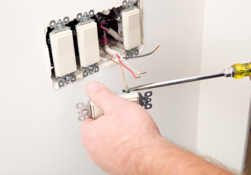
Step 2: Pull Out the Old Switch
-
Remove the mounting screws that hold the switch to the box. Gently pull the switch
forward, leaving the wires connected so you can see how everything is currently
arranged. -
Take a clear photo with your phone of the existing wiring. Future you will thank
you.
Step 3: Identify and Label Each Wire
Before disconnecting anything, label the wires:
-
Find the wire attached to the common terminal (the screw is usually
darker or marked “COM”). Mark this wire with a piece of tape labeled “COMMON.” -
The remaining two insulated wires on the switch are the
travelers. Label them “TRAVELER 1” and “TRAVELER 2.” The exact
order isn’t critical as long as you connect them consistently on the new switch. -
Identify the ground wire (bare copper or green) attached to the
green screw and mark it if necessary. -
Note any neutral bundle (white wires tied together with a connector)
in the back of the box. These usually remain untouched when replacing the switch.
Do this labeling at both switch locations. Treat each box as its own little puzzle.
Step 4: Disconnect the Old Switch
-
Once everything is labeled, loosen the terminal screws or release any push-in
connectors to free the wires from the old switch. -
Check the copper ends of the wires. If they’re nicked, corroded, or bent badly, trim
and restrip the ends according to the switch manufacturer’s instructions (often about
1/2 inch of bare copper).
Step 5: Connect Wires to the New 3-Way Switch
Now transfer each wire to the matching terminal on the new switch:
-
Attach the COMMON-labeled wire to the black (or darkest) screw
terminal labeled “COM” or “COMMON.” -
Attach the two traveler wires to the two brass-colored traveler
terminals. Keep the same orientation you observed on the old switch if possible
(e.g., the red traveler on top in both boxes). - Attach the ground wire to the green grounding screw.
Tighten all screws firmly so the wires don’t wiggle. Loose connections can cause
flickering lights and overheating.
Step 6: Fold the Wires and Reinstall the Switch
-
Carefully fold the wires back into the box in an accordion or “S” shape so they fit
without sharp bends or strain on the connections. -
Position the switch so “up” corresponds to the correct orientation (if there’s a
label) and secure it to the box with the mounting screws. - Reinstall the wall plate, being careful not to overtighten and crack it.
Step 7: Repeat on the Second Switch
Go to the other 3-way switch location and repeat the same process: power off checked,
label, disconnect, reconnect to the new switch, and reassemble. The travelers between
the boxes should stay on traveler screws; the common wire will either be the line from
the panel or the load going to the light, depending on the box.
Step 8: Restore Power and Test the Circuit
- Turn the breaker back on.
-
Test the switches: flip Switch A on, then Switch B; then reverse. In any combination,
you should be able to turn the light on and off from either location.
If the light only works in certain positions, the travelers or common wire may be on
the wrong terminal. Turn the power back off and double-check your labels and
connections.
Common Mistakes to Avoid
-
Mixing up the common and traveler wires. This is the number-one
cause of strange behavior. Always identify the common before disconnecting the old
switch. -
Leaving neutrals loose or disconnected. Neutrals should remain tied
together securely inside approved connectorsnever hanging loose. -
Overstuffing the box. Every box has a volume rating. If there are
too many wires and devices, you may need a larger box to stay code-compliant. -
Using the wrong switch type. Don’t replace a 3-way with a standard
single-pole switch. A 3-way switch clearly has three active terminals plus ground. -
Skipping the voltage test. “I turned off the breaker” is not a
test. Always verify with a tester before touching wires.
When You Should Call an Electrician
Even confident DIYers sometimes hit a point where calling a pro is the smartest move.
Consider hiring a licensed electrician if:
- The wiring in the box doesn’t resemble any standard diagram you’ve seen.
-
You discover aluminum wiring, knob-and-tube, or other older systems that have special
rules. - The circuit keeps tripping the breaker or the switch feels hot to the touch.
- Local codes require a licensed pro for alterations to electrical circuits.
- You simply don’t feel comfortable. That’s reason enough.
A short service visit from an electrician is far cheaper than repairing damage from an
electrical fire or shock incident.
Upgrading 3-Way Switches: Dimmers and Smart Controls
Once you understand the basics of 3-way switch wiring, you can consider upgrades:
-
3-way dimmer switches – Special dimmers are designed to work with a
companion 3-way switch or a matching remote. Always follow the manufacturer’s wiring
diagram, as terminals may be labeled differently than standard switches. -
Smart 3-way switches – Many Wi-Fi or Z-Wave smart switches can
replace one or both of your 3-way switches, but they often require a neutral and have
very specific wiring requirements. Carefully check compatibility, especially in older
homes.
For any advanced device, treat the included installation sheet as your “final boss”
referencethis article gives you the theory, but the manufacturer’s diagram is the last
word on which wire goes where.
Real-World 3-Way Switch Wiring Experiences (Extra Tips)
Theory is great, but the real world is where things get interesting. Here are some
experience-based tips and scenarios to help you navigate the quirks that rarely show up
in neat wiring diagrams.
1. The “Mystery White Wire” That Isn’t Neutral
Many DIYers open a switch box and assume every white wire is neutral. In older or more
creative installations, a white wire may actually be carrying hot power as part of a
3-way or “switch loop” configuration. It may (or may not) be marked with black tape.
If a white wire goes to a switch terminal instead of a bundle of neutrals, treat it as
a potential hot until proven otherwise with a tester. Don’t move or re-identify it
unless you’re sure what it does. When in doubt, get an electrician to confirm the
function of each conductor.
2. Labeling Is Your Best Friend
A lot of frustration comes from disconnecting everything at once and then trying to
remember where each wire was. Experienced electricians often work on only one wire at a
time for a reason.
A solid DIY strategy:
- Photograph the switch and box before touching anything.
- Label each wire as you remove it from the old switch.
-
Keep old switches until the new ones are installed and workingjust in case you need
to compare terminal layout.
This takes a few extra minutes up front and can save you hours of troubleshooting later
(and possibly a panicked call to a pro).
3. Tight Boxes and Stiff Wires
Older homes sometimes have shallow metal boxes and stiff, thick copper wiring. Getting
a new switch and all the wires to fit comfortably can feel like trying to stuff a
sleeping bag back into its original sack.
A few tricks:
-
Pre-fold the wires in a zigzag pattern so they tuck neatly into the back and sides of
the box. -
Use compact, listed wire connectors (like lever-style connectors) to reduce bulk
compared with oversized wire nuts. -
If you absolutely cannot fit everything without excessive force, talk to an
electrician about replacing the box with a larger, code-compliant one.
4. Troubleshooting Weird Switch Behavior
After rewiring, you might run into odd behavior:
-
Light only works when both switches are in certain positions – usually means the
common and a traveler are swapped at one of the switches. -
Light never comes on – check the common on both switches and confirm the load wire to
the light is on a common terminal, not a traveler. -
Breaker trips when you flip the switch – there may be a short or a neutral/hot mix-up
somewhere. Turn off power immediately and recheck, or call a pro.
Experienced electricians often approach problems methodically: they identify which
cable is the power feed, which goes to the light, and which is the traveler cable
between boxes. With a tester and some patience, you can do the samebut if it starts
to feel like a logic puzzle gone wrong, it’s okay to hand it off.
5. Plan for the Future
When you’re already working on 3-way switch wiring, it’s a good time to think ahead.
If you suspect you’ll eventually want smart controls or additional lighting loads, talk
with an electrician now about:
- Ensuring neutrals are present in each switch box (many smart switches require them).
- Verifying box fill is adequate for future devices.
- Checking that breakers and wiring are appropriately sized for any added fixtures.
Planning with the long view in mind can save you from opening up the same walls twice.
Conclusion
3-way switch wiring looks complicated at first glance, but once you understand the
roles of the common terminal, traveler wires, and neutral and ground, it starts to
make sense. For many homeowners, simply replacing existing 3-way switches is a safe
and achievable weekend project, as long as you:
- Turn off and verify power before working.
- Label every wire before disconnecting it.
- Match each wire to the correct terminal on the new switch.
- Follow the switch manufacturer’s instructions and local codes.
Respect electricity, work slowly, and don’t hesitate to call in a licensed electrician
if anything looks confusing or unsafe. When you’re done, you’ll have a properly wired
3-way circuit that lets you control your lights from two locationsand the satisfaction
of knowing exactly how it all works behind the wall.