Table of Contents >> Show >> Hide
- What Does “From Scratch” Really Mean?
- How GPS Works in Plain English
- The GPS L1 C/A Signal: The Classic Starting Point
- The Basic Architecture of a Software GPS Receiver
- Common Challenges When Writing a GPS Receiver
- Useful Tools and Languages
- A Practical Development Roadmap
- Specific Example: The First Acquisition Test
- Why Build a GPS Receiver Instead of Buying One?
- Experiences and Lessons From Writing A GPS Receiver From Scratch
- Conclusion
Writing a GPS receiver from scratch sounds like one of those engineering ideas that begins with optimism, coffee, and a dangerous misunderstanding of the word “simple.” After all, your phone finds your location in seconds. Your car tells you where to turn. A tiny running watch knows whether you crossed the street or merely wobbled near the curb. So how hard can it be?
As it turns out, building a GPS receiver is not just “listening to satellites.” It is a full-stack adventure through radio-frequency hardware, digital signal processing, timing systems, orbital mechanics, error correction, and enough matrix math to make a calculator quietly fake its own death. But it is also one of the most rewarding projects an engineer, student, radio hobbyist, or deeply curious maker can attempt.
A GPS receiver built from scratch teaches you how invisible signals become latitude, longitude, altitude, velocity, and time. It reveals why GPS is not magic, even though it occasionally behaves like it. This guide walks through the major ideas behind building a software-defined GPS receiver, including the signal chain, C/A code acquisition, tracking loops, navigation message decoding, pseudorange calculation, and position solving. We will keep things practical, honest, and just fun enough that the math does not start throwing chairs.
What Does “From Scratch” Really Mean?
Before grabbing an antenna and declaring yourself mission control, it helps to define the project. Writing a GPS receiver from scratch usually means implementing the receiver logic yourself, often in software, while still using some hardware to capture the radio signal. In other words, you are not launching satellites or manufacturing an RF front end in your garage. Your neighbors may already have questions; no need to add “space program” to the list.
A typical from-scratch GPS receiver project uses a GNSS antenna, a low-noise amplifier, an SDR device or custom RF front end, and software that processes raw intermediate-frequency or baseband samples. The software performs the jobs that a commercial GPS chip normally hides: signal acquisition, tracking, bit synchronization, frame synchronization, navigation decoding, pseudorange estimation, satellite position calculation, and final position solution.
This is why software-defined radio is such a powerful approach. Instead of locking yourself into a fixed chip design, you can inspect every stage of the receiver chain. You can plot correlations, debug Doppler bins, adjust loop bandwidths, test different algorithms, and learn exactly where your receiver is succeeding or face-planting into the digital floor.
How GPS Works in Plain English
The Global Positioning System is a U.S.-owned satellite navigation system that provides positioning, navigation, and timing services. It has three major parts: the space segment, the control segment, and the user segment. The space segment is the constellation of satellites broadcasting radio signals. The control segment monitors and updates the satellites. The user segment is everything from your phone to survey equipment to the experimental GPS receiver you are bravely writing while muttering at complex numbers.
Each GPS satellite broadcasts a signal that includes two crucial pieces of information: the time the signal was transmitted and data that lets the receiver calculate where the satellite was when it transmitted. A receiver compares the satellite transmission time with its own receive time. The difference, multiplied by the speed of light, gives a rough distance called a pseudorange.
Why “pseudo”? Because the receiver clock is not perfect. A satellite carries an extremely stable clock; your homemade receiver probably carries an oscillator that has strong opinions and mild emotional instability. The receiver therefore solves not only for three-dimensional position but also for receiver clock bias. That is why a basic GPS position fix generally needs signals from at least four satellites.
The GPS L1 C/A Signal: The Classic Starting Point
Most beginner software GPS receiver projects start with the legacy GPS L1 C/A signal. It is publicly available, widely documented, and centered at 1575.42 MHz. The C/A code is a pseudorandom noise code transmitted at 1.023 million chips per second, repeating every millisecond. Each satellite has its own PRN code, allowing a receiver to separate satellites that are broadcasting on the same frequency.
That last point is important. GPS satellites do not politely take turns like people at a well-run dinner party. Multiple satellites transmit at the same carrier frequency. The receiver identifies each one by correlating incoming samples with locally generated copies of each satellite’s PRN code. When the local code lines up with a real satellite signal, a correlation peak appears. That peak is the receiver’s first little victory dance.
The L1 C/A signal also carries a navigation message at 50 bits per second. Yes, 50. Not megabits. Not kilobits. Bits. A GPS receiver is not downloading cat videos from orbit. It is patiently decoding satellite clock data, ephemeris data, almanac data, health information, and timing information. The slow rate is one reason a cold-start receiver may take time to compute its first fix.
The Basic Architecture of a Software GPS Receiver
A from-scratch receiver can be divided into a clean pipeline. The exact design varies, but most GPS software receivers include the following stages:
1. RF Front End and Sampling
The antenna receives extremely weak satellite signals. These signals are below the noise floor, which sounds impossible until spread-spectrum processing enters the room wearing a cape. A low-noise amplifier boosts the signal, and an RF front end downconverts it from L1 to an intermediate frequency or baseband. The SDR then digitizes the result into I/Q samples.
Sample rate matters. Too low, and you lose useful signal detail. Too high, and your CPU begins negotiating better working conditions. Many hobby projects use affordable SDR hardware, but not every cheap dongle can receive GPS L1 directly without the right tuner, bias tee, antenna, and filtering. A stable oscillator is also important because receiver frequency error adds to Doppler uncertainty.
2. Signal Acquisition
Acquisition answers three questions: Which satellites are visible? What is the code phase? What is the Doppler shift? The receiver searches across PRN codes, code delays, and Doppler frequency bins. For each combination, it correlates the incoming signal with a locally generated PRN replica.
If the correlation result crosses a detection threshold, the receiver has likely found a satellite. The output of acquisition is a coarse estimate of code phase and Doppler. Coarse is good enough here; acquisition is the handshake, not the marriage.
Efficient acquisition often uses FFT-based circular correlation. Instead of sliding every possible code phase in the slowest way imaginable, the receiver transforms data into the frequency domain and performs correlation much faster. This is where GPS development starts feeling like digital signal processing with a side order of treasure hunting.
3. Tracking Loops
After acquisition, tracking keeps the receiver locked onto each satellite signal. The satellite and receiver are moving, clocks drift, and the signal environment changes. Tracking continuously refines code phase, carrier frequency, and carrier phase.
A classic GPS receiver uses a delay lock loop for code tracking and a phase lock loop or frequency lock loop for carrier tracking. The delay lock loop keeps the local PRN code aligned with the incoming code. The carrier loop removes Doppler and oscillator effects so the navigation data can be recovered.
Tracking is where many homebuilt receivers earn their scars. Loop bandwidths that are too narrow may lose lock during dynamics. Loop bandwidths that are too wide may chase noise like a puppy chasing a leaf blower. Good tracking design is a balance between responsiveness and stability.
4. Navigation Bit Decoding
Once a channel is tracking a satellite, the receiver can begin decoding the navigation message. Since the C/A code repeats every millisecond and the navigation data rate is 50 bits per second, each navigation bit spans 20 milliseconds. The receiver integrates tracking outputs, detects bit transitions, finds frame boundaries, and extracts navigation words.
The navigation message includes ephemeris data for the transmitting satellite, satellite clock correction terms, GPS time information, and almanac data for the broader constellation. Ephemeris is especially important because it tells the receiver how to compute the precise satellite position at the time of transmission.
5. Pseudorange Measurement
With tracking and timing information in place, the receiver estimates pseudorange for each satellite. Pseudorange is based on signal travel time, but practical measurement requires careful handling of code phase, navigation frame timing, receiver sampling time, and clock bias.
A simple receiver may begin with code-phase pseudoranges. More advanced receivers can use carrier-phase measurements, smoothing, dual-frequency corrections, or external assistance. For a first from-scratch project, code-phase pseudorange is already a respectable mountain to climb. Bring snacks.
6. Satellite Position Calculation
Using decoded ephemeris parameters, the receiver computes each satellite’s Earth-centered, Earth-fixed position at the signal transmission time. This step involves orbital equations, clock corrections, relativistic corrections, and Earth rotation compensation. It is not enough to know where the satellite is “now”; the receiver needs where it was when the signal left the satellite.
Because GPS signals travel at light speed but still take measurable time to reach Earth, timing errors become distance errors very quickly. One nanosecond corresponds to roughly one foot of signal travel. GPS is therefore a positioning system that moonlights as a ruthless timing exam.
7. Position Solution
Finally, the receiver solves for user position and clock bias. With four or more satellites, it can use iterative least squares to estimate x, y, z coordinates and receiver clock offset. These coordinates are usually solved first in an Earth-centered coordinate system and then converted to latitude, longitude, and altitude.
The solution may need several iterations because the equations are nonlinear. Once the receiver converges, you get the reward: an actual position fix produced by your own code from raw satellite signals. At this point, it is acceptable to look smugly at a commercial GPS module. Quietly, though. It did this using a speck of silicon and almost no power.
Common Challenges When Writing a GPS Receiver
Weak Signals
GPS signals arrive at Earth incredibly weak. The receiver depends on correlation gain from the PRN codes to pull signals out of noise. A poor antenna, bad cable, weak amplifier, or noisy front end can make acquisition painfully unreliable.
Frequency Error and Doppler
The receiver must search Doppler offsets caused by satellite motion and receiver oscillator error. A low-quality oscillator can widen the search range and make tracking less stable. This is one reason disciplined oscillators and better SDR hardware can dramatically improve results.
Multipath
Multipath happens when GPS signals bounce off buildings, vehicles, water, or other surfaces before reaching the antenna. The receiver may see delayed versions of the same signal, which can distort code tracking and pseudorange estimates. Urban canyons are basically multipath theme parks, except no one has fun.
Navigation Message Patience
At 50 bits per second, decoding ephemeris requires patience and stable tracking. Losing lock halfway through a subframe is like dropping a puzzle piece into a heating vent. You may recover, but there will be sighing.
Coordinate Systems
A GPS receiver touches several coordinate and time systems. GPS time, UTC offsets, Earth-centered Earth-fixed coordinates, geodetic latitude and longitude, satellite orbital frames, and receiver local time all need careful treatment. Bugs here can produce positions that are wrong in very creative ways.
Useful Tools and Languages
You can write a GPS receiver in C, C++, Python, Rust, MATLAB, or almost any language with strong numerical and signal-processing support. Python is friendly for experiments and plotting, though performance-critical acquisition may need NumPy, FFT libraries, C extensions, or GPU acceleration. C and C++ are common for real-time receivers because they offer speed and control.
Open-source projects such as GNSS-SDR are valuable references because they show how full receiver chains are organized in practice. Even if your goal is to write everything yourself, studying mature receiver architectures helps prevent design choices that later corner you like a raccoon in a pantry.
For testing, simulated GPS signals are extremely useful. A simulator lets you control satellite visibility, Doppler, noise, and receiver motion. Recorded sample files are also helpful because they let you replay the same scenario while debugging. Live-sky testing is exciting, but repeatability is the difference between engineering and superstition with graphs.
A Practical Development Roadmap
Start With Offline Processing
Do not begin with real-time ambitions unless you enjoy debugging while your data runs away. Capture a short sample file and process it offline. First, verify sample format, center frequency, sample rate, and basic spectrum. Then implement PRN generation and acquisition.
Acquire One Satellite
Find one strong satellite. Plot the correlation peak. Confirm that Doppler and code phase estimates make sense. This single success proves your front end, PRN generator, sample handling, and acquisition logic are at least speaking the same language.
Track One Channel
Build a tracking loop for that satellite. Watch prompt, early, and late correlator outputs. Monitor carrier wipeoff, code alignment, discriminator values, and lock indicators. Tracking graphs are your dashboard; without them, you are driving through fog with a kazoo for a horn.
Decode Navigation Data
Once tracking is stable, extract navigation bits. Detect preambles, verify parity, identify subframes, and parse ephemeris. This stage can feel slow, but it transforms your receiver from “signal detector” into “navigation instrument.”
Add More Satellites
Duplicate tracking channels for multiple acquired satellites. Compute pseudoranges and satellite positions. Then implement least-squares positioning. Your first fix may be rough, but even a rough fix from your own receiver is a wonderful moment.
Improve Accuracy and Robustness
After the first fix, improve everything. Add better filtering, C/N0 estimation, lock detection, elevation masks, ionospheric and tropospheric models, satellite health checks, outlier rejection, and smoother timing. This is where a science project begins evolving into a receiver.
Specific Example: The First Acquisition Test
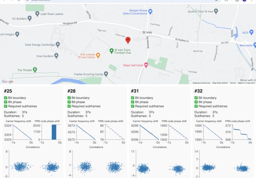
Suppose you record GPS L1 samples at an intermediate frequency. You generate the C/A code for PRN 7. Then you search Doppler bins from -5 kHz to +5 kHz in 500 Hz steps. For each Doppler bin, you mix the samples to remove that frequency offset, correlate the result with the PRN code over one millisecond, and look for a strong peak.
If PRN 7 is visible, one Doppler bin and one code phase should stand out. The code phase tells you where the PRN pattern aligns in your sample buffer. The Doppler estimate tells you how much the signal frequency differs from nominal. Feed those estimates into a tracking channel, and the receiver can begin following the satellite continuously.
This is the first “aha” moment. A signal that looked like noise suddenly reveals structure. The satellite was there all along, whispering through the static like a very expensive bird.
Why Build a GPS Receiver Instead of Buying One?
Buying a GPS module is cheap, easy, and sensible. Writing a GPS receiver from scratch is none of those things. But it gives you something a module cannot: understanding.
You learn how spread-spectrum systems work, why timing dominates positioning, how satellite orbits become coordinates, why receiver clocks matter, and how weak signals can be recovered through correlation. You also gain a practical education in SDR, estimation theory, numerical optimization, and embedded systems design.
For students, it is a portfolio project with serious technical depth. For engineers, it is a way to understand GNSS performance and limitations. For hobbyists, it is a satisfying climb. For anyone who has ever stared at a blue dot on a map and wondered how it got there, it is the long answer.
Experiences and Lessons From Writing A GPS Receiver From Scratch
The first experience most people have when writing a GPS receiver from scratch is humility. The second is usually a file full of raw I/Q samples that looks completely useless. This is normal. GPS signals do not appear as neat little waveforms waving hello. They are spread below the noise floor, and your job is to convince mathematics to admit they exist.
One of the biggest lessons is that plotting is not optional. Plot the spectrum. Plot acquisition heat maps. Plot correlation peaks. Plot tracking loop errors. Plot navigation bits. Plot residuals after the position solution. A GPS receiver without visualization is like a mechanic diagnosing an engine by listening from another zip code. You might guess correctly, but you will suffer dramatically first.
Another hard-earned lesson is to test each stage separately. When beginners try to build the whole pipeline at once, every bug disguises itself as every other bug. A wrong PRN generator can look like an RF problem. A sample format mistake can look like failed acquisition. A sign error in carrier wipeoff can look like bad Doppler. A timing bug can move your computed position to another state, which is exciting only if you enjoy fictional travel.
Start with known-good data whenever possible. If you can process a sample file that other receivers have already used successfully, you remove a lot of uncertainty. Once your software works on known data, move to your own recordings. This approach keeps you from blaming your code for antenna problems or blaming the antenna for code that is quietly upside down.
Hardware placement also matters more than expected. A GPS antenna near a window may work, but a roof or open-sky view is much better. Buildings, metal objects, trees, and even nearby electronics can reduce signal quality. Multipath is especially sneaky because the receiver may still acquire and track signals, but the pseudoranges become biased. The result is not failure; it is worse. It is confidence with wrong numbers.
Timing discipline is another major lesson. GPS is not only a positioning system; it is a time measurement system with geography attached. If your sample counter, millisecond boundary, navigation bit timing, or receiver clock model is sloppy, the final position will complain. Sometimes it complains politely through residuals. Sometimes it throws your location into the ocean.
Performance optimization usually arrives later than expected. A simple acquisition routine may work beautifully on one PRN and one millisecond of data, then become painfully slow when searching all visible satellites across many Doppler bins. FFT-based acquisition, vectorized code, parallel processing, and careful memory layout eventually become important. The trick is not to optimize too early. First make it correct. Then make it fast. Then make it less embarrassing.
One satisfying milestone is decoding your first navigation subframe. Another is computing your first satellite position from ephemeris. But the unforgettable moment is the first position fix. Even if it is off by a few hundred meters, it feels like discovering fire, except the fire is a least-squares solver and it probably has a bug. From there, every improvement becomes measurable: better acquisition thresholds, cleaner tracking, more stable pseudoranges, lower residuals, and a position that gradually walks toward reality.
The best practical advice is to treat the receiver as a chain of evidence. Each block should produce outputs that can be inspected and verified. Acquisition should produce believable peaks. Tracking should produce stable discriminator outputs. Decoding should pass parity checks. Pseudoranges should be consistent. Position residuals should make sense. When one stage becomes mysterious, slow down and instrument it.
Writing a GPS receiver from scratch is difficult, but it is not impossible. It is a layered project where each layer teaches something valuable. You begin with noise. You end with position, velocity, and time. In between, you learn that satellites are precise, clocks are unforgiving, and radio waves have a mischievous sense of humor.
Conclusion
Writing a GPS receiver from scratch is one of the clearest ways to understand modern satellite navigation. It combines radio hardware, software-defined radio, signal processing, tracking loops, navigation data decoding, orbital calculations, and numerical positioning into one ambitious project. The challenge is real, but so is the payoff.
A beginner should start with the GPS L1 C/A signal, work offline with captured samples, acquire one satellite, build stable tracking, decode navigation data, and only then attempt a full position fix. The project rewards patience, careful testing, and a willingness to stare at plots until they confess.
In the end, a homemade GPS receiver is more than code. It is a working explanation of how a faint signal from space becomes a blue dot on Earth. And once you have built that yourself, ordinary navigation apps feel a little less ordinary.