
Table of Contents >> Show >> Hide
- What People Really Mean by “Every Connector”
- The Connector Families That Actually Matter
- What the Ideal Board Would Include
- Why “Every Connector” Can Go Wrong
- Real-World Design Lessons From Existing Boards
- How to Choose or Design Your Own Universal Prototyping Board
- Conclusion
- Experience Notes: Living With the “Board With Every Connector” Idea
Every engineer, maker, and serial tinkerer has had this thought at least once: “What if I had one prototyping board with every connector I could possibly need?” It is the electronics equivalent of wanting one kitchen drawer that holds every spoon, whisk, knife, spatula, and mysterious gadget you bought at 2 a.m. and swore you would use. The dream is understandable. Modern prototyping moves fast, but the connector landscape can feel like a family reunion where nobody wears name tags. One sensor wants Grove. Another prefers Qwiic. A dev board insists on 0.1-inch headers. Your display demands SPI. Your debugger wants SWD. Your laptop only brought USB-C to the party. Suddenly, your “quick prototype” looks like a nest of jumpers auditioning for a disaster movie.
That is why the idea of a prototyping board with every connector is so appealing. Not because engineers are lazy, but because modern hardware work rewards flexibility. The more interfaces a board can expose cleanly, the faster you can test a sensor, swap a display, add wireless, measure power, and move from “interesting idea” to “working prototype” before lunch gets cold. But there is a catch: a board with every connector is only useful if those connectors are chosen intelligently. More ports do not automatically mean more progress. Sometimes they just mean more ways to plug the wrong thing into the wrong place and create instant sadness.
So what would a truly useful “prototyping board with every connector” look like? And more importantly, which connectors actually deserve a seat at the table? Let’s build the case, one socket at a time.
What People Really Mean by “Every Connector”
No board can literally include every connector in electronics. That way lies madness, oversized PCBs, and probably a small forklift. In practice, what people want is a board that bridges the major prototyping worlds: breadboard-friendly headers, modern USB for power and programming, quick-connect sensor ports, standard peripheral sockets, and expansion headers that let the board grow with the project.
A smart universal prototyping board should not try to be infinite. It should try to be useful. That means covering the connectors people actually use during evaluation, proof-of-concept work, classroom builds, embedded firmware testing, and early product design. The best versions do not just expose pins. They reduce friction. They let you move between ecosystems without spending the afternoon crimping cables, swapping adapters, or muttering at silkscreen labels under bad desk lighting.
The Connector Families That Actually Matter
1. USB-C for Power, Programming, and Sanity
If a modern prototyping board does not start with USB-C, it already feels like it got dressed in 2014. USB-C earns its place because it is reversible, compact, widely available, and increasingly expected on development hardware. For many prototypes, USB-C handles the unglamorous but essential jobs: powering the board, flashing firmware, opening a serial console, and sometimes carrying higher-speed data or negotiated power.
It also helps future-proof a design. A board that begins with USB-C feels more at home on current desks, in classrooms, and in labs where nobody wants to hunt for a micro-USB cable like it is an archaeological artifact. The caveat is that USB-C is not just “a nicer plug.” If the board uses it properly, designers must think about power roles, current limits, signal routing, ESD protection, and whether the connector is there for simple USB 2.0, power delivery, or something fancier. In other words, USB-C is wonderful, but it demands respect. This connector is not a decorative necklace for your PCB.
2. 0.1-Inch Headers: The Cockroaches of Electronics, in the Best Way
Standard 2.54 mm, or 0.1-inch, headers refuse to go extinct, and frankly, good for them. These headers remain essential because breadboards, perfboards, jumper wires, logic analyzers, cheap modules, and countless hobby-to-professional tools still revolve around this spacing. When people say they want a board that works with everything, this is usually what they mean at the physical level.
A great prototyping board should expose GPIO, power rails, analog inputs, common serial interfaces, and debug pins on clearly labeled header rows. Bonus points if the board is breadboard-friendly, which means the pin spacing and width do not force users into a geometry puzzle just to connect a sensor. Headers may not look glamorous next to fancy keyed connectors, but they are still the most democratic interface in electronics. They say, “Come as you are. Bring your jumper wires.”
3. Qwiic and STEMMA QT for Fast I2C Prototyping
If headers are the universal handshake, Qwiic and STEMMA QT are the VIP fast-pass lane. Both are built around a simple idea: many sensors and small peripherals use I2C, so why make people wire power, ground, SDA, and SCL manually every single time? These compact 4-pin cable systems make it easy to connect compatible parts quickly, neatly, and with less opportunity for human creativity in the “whoops, I reversed the wires” category.
This style of connector is especially valuable for rapid experimentation. You can swap sensors, chain several devices together, and keep the wiring compact enough that your prototype still resembles engineering instead of modern abstract art. For beginners, it lowers the barrier to entry. For experienced users, it saves time. For everyone, it reduces the odds of a mystery bug caused by one loose jumper that looked innocent but was spiritually committed to chaos.
4. Grove for Modular Plug-and-Play Builds
Grove deserves a place on the “every connector” dream board because it covers a broader plug-and-play prototyping style. Where Qwiic and STEMMA QT are commonly associated with compact I2C connections, Grove has built an expansive ecosystem around standardized connectors for digital, analog, I2C, UART, and other module types. That makes it particularly useful in education, quick demos, and mixed-signal projects where users want modularity without a wiring tangle.
A board that includes a few Grove ports instantly becomes more welcoming to off-the-shelf modules. It is a practical bridge between beginners who want clean assembly and advanced users who need to test ideas quickly. And yes, sometimes convenience really is a feature. The best prototype is often the one you can build before motivation wanders off to watch videos about keyboards or mechanical pencils.
5. Pmod and mikroBUS for Serious Expansion
Once a project grows beyond simple sensor hookups, standards like Pmod and mikroBUS start to shine. These ecosystems are designed for modular add-on boards that carry a single function or tightly grouped feature set, such as displays, comms, storage, motor control, sensing, or interface logic. They offer a more structured expansion path than loose header wiring and can be a gift to anyone who wants repeatable, semi-professional prototyping without jumping straight to a custom daughterboard.
Pmod is particularly handy for lower-pin-count peripherals, while mikroBUS has become famous for its broad add-on ecosystem. Including one or both sockets on a universal prototyping board adds real value because it lets the board serve as a central hub rather than just a breakout slab. If headers are a blank canvas, Pmod and mikroBUS are like having a box of clean, labeled Lego bricks instead of a bag of random screws.
6. Shield-Style and Form-Factor Headers
Expansion headers tied to major form factors matter because ecosystems matter. Arduino-compatible headers, Feather-style layouts, Nano footprints, and similar standards help users build on what they already own. A board with every connector should not live in isolation like a genius hermit. It should play nicely with shields, carriers, wings, and other expansion hardware already sitting in parts bins around the world.
This is where the best carrier and proto boards excel. They combine traditional header access with more modern modular connectors, allowing one board to support quick experiments and more structured subsystem testing at the same time. That blend is powerful. It means the board is not just “compatible.” It is socially well-adjusted.
What the Ideal Board Would Include
A genuinely practical prototyping board with every connector would probably include:
- USB-C for power, data, and programming
- Clearly labeled 0.1-inch GPIO headers
- At least one or two Qwiic or STEMMA QT ports
- Multiple Grove connectors for modular peripherals
- A Pmod socket for quick digital expansion
- A mikroBUS socket for wider add-on support
- Debug access such as SWD, JTAG, UART, or tag-connect pads
- Dedicated power rails with 3.3 V and 5 V labeling
- Level shifting or at least clear voltage-domain warnings
- Mounting holes, because prototypes deserve dignity too
Add a small prototyping area, good silkscreen, power measurement jumpers, ESD protection on the external ports, and sane connector spacing, and now we are talking about a board that can live on a bench for months without becoming a source of resentment.
Why “Every Connector” Can Go Wrong
Here is the twist: adding connectors is easy. Adding them well is hard. The universal-board fantasy falls apart when designers ignore signal integrity, voltage compatibility, routing complexity, mechanical strength, and sheer user confusion. Not every connector wants to share a neighborhood. Some need short traces. Some carry different voltages. Some expect pull-up resistors. Some assume hot-plug behavior. Some are ideal for sensors but terrible for motors or fast displays.
Then there is the layout problem. If you cram every port onto one board, users may gain options but lose clarity. A great prototyping board should feel obvious. You should be able to glance at it and know where to power it, where to attach a sensor, where to probe a signal, and where not to plug a 5 V device into a 3.3 V rail unless you enjoy educational smoke.
In other words, the best “board with every connector” is not the one with the most holes. It is the one that separates functions sensibly, labels everything cleanly, and helps the user avoid expensive experiments in accidental reverse engineering.
Real-World Design Lessons From Existing Boards
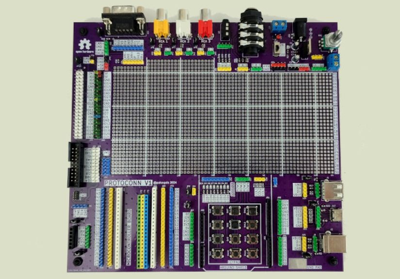
The hardware world already offers clues about what works. Some compact development boards pair USB-C with quick I2C connectors, making them fantastic for sensor-heavy builds. Others combine classic shield headers with specialized expansion sockets, which is excellent for stacking and subsystem testing. Still others prioritize breadboard compatibility, exposing major pins on standard spacing so the board can drop into a solderless workflow immediately.
The lesson is simple: the strongest boards do not try to replace every ecosystem. They bridge them. A board that gives you USB-C, standard headers, one compact I2C connector system, and one structured expansion standard already solves most real prototyping pain points. Add good documentation and pin labeling, and that board becomes the one users reach for first instead of the one they discover six months later in a drawer under three anti-static bags and a cable of unknown origin.
How to Choose or Design Your Own Universal Prototyping Board
If you are shopping for a board like this, or planning to design one, start by asking what kinds of prototypes you actually build. If you work mostly with sensors, prioritize I2C-friendly connectors, voltage clarity, and clean power rails. If you test displays, radios, storage, or digital modules, expansion standards like Pmod or mikroBUS become more valuable. If your workflow revolves around jumper-wire experiments and quick firmware tests, breadboard-friendly headers and USB-C may matter more than fancy sockets.
Also think about who will use the board. A classroom board benefits from clear modular connectors and protection against common mistakes. A lab board may need more debug access, isolated measurement points, and easy reconfiguration. A startup team working on proof-of-concept hardware may want a board that lets firmware, mechanical, and electrical work happen in parallel without everyone fighting over one fragile setup.
The smartest universal board is not universal because it supports everything equally. It is universal because it supports the most important things gracefully.
Conclusion
A prototyping board with every connector is less a single mythical product and more a design philosophy. The goal is not connector hoarding. The goal is removing friction between ideas and working hardware. A well-chosen mix of USB-C, standard headers, fast sensor connectors, modular peripheral sockets, and ecosystem-friendly expansion headers can turn one board into an incredibly capable launchpad for real projects.
The trick is restraint. The board should not try to be a museum of connector history. It should focus on the interfaces that actually help people prototype faster, debug more easily, and adapt when projects inevitably change direction halfway through. Because they will. They always do. The board that survives that chaos is the board worth keeping.
So yes, the dream of a prototyping board with every connector makes sense. Just remember that the best version of that dream is not “everything everywhere all at once.” It is “the right things, in the right places, with the right labels, so your next prototype has a fighting chance.”
Experience Notes: Living With the “Board With Every Connector” Idea
My favorite thing about the “every connector” concept is that it usually starts with optimism and ends with humility. The first time you sketch one of these dream boards, you feel unstoppable. You add USB-C, a couple of sensor ports, a big header row, maybe a socket for a display module, and suddenly you are not designing a board anymore, you are building a tiny electronics city. On paper, it looks brilliant. In real life, you learn that every connector comes with baggage: one needs pull-ups, another needs careful orientation, another steals precious board space, and another is mechanically strong only until someone yanks a cable sideways during debugging.
In actual prototyping work, the most useful boards are rarely the ones that try to impress you in a product photo. They are the ones that quietly save you time. A well-placed USB-C port means you are powered and programming in seconds. A clean row of labeled headers means you can clip on a logic analyzer without performing finger yoga. A Qwiic, STEMMA QT, or Grove connector means you can swap a sensor in twenty seconds instead of five minutes. That difference sounds small until you do it fifteen times in one afternoon and realize the board just saved your mood.
I have also learned that connector variety changes how people behave around a project. Beginners get bolder when they see ports that look intentional and friendly. They are more willing to try things when they do not have to decode a forest of pins first. Experienced users benefit too, just in a different way. They stop wasting time on repetitive wiring and spend more time validating ideas, checking timing, measuring current, and deciding what belongs in the next revision.
There is also a surprising psychological advantage to a board that bridges multiple ecosystems. It reduces commitment anxiety. You do not have to decide on day one whether the project will live in a shield-based world, a sensor-cable world, or a bare-header world. You can explore. You can prototype a temperature logger with a quick-connect sensor today, then bolt on a display tomorrow, then move part of the design onto perfboard next week. That freedom matters, because early hardware projects are messy by nature. The universal board does not eliminate the mess, but it gives it some adult supervision.
Of course, the fantasy can go too far. I have seen boards with so many connectors that using them felt like navigating an airport terminal designed by a committee that hated maps. When every edge of the PCB contains a different socket, the user spends more time studying the board than building the project. That is when the “every connector” idea stops being helpful and becomes decorative chaos. The best boards are edited. They choose the interfaces people actually reach for, then support them with readable silkscreen, sane spacing, and enough room for probes, fingers, and the occasional debugging sigh.
In the end, the real experience of using a prototyping board with every connector is not about bragging rights. It is about momentum. The right board keeps your prototype moving. It lets you change direction without starting over. It gives your experiments a sturdy home while your idea is still figuring out what it wants to be. And honestly, that is the whole game in prototyping: not perfection, not elegance, just a board that helps good ideas survive long enough to become real hardware.